Thread | ||||||||||||||||||||||||||
| ||||||||||||||||||||||||||
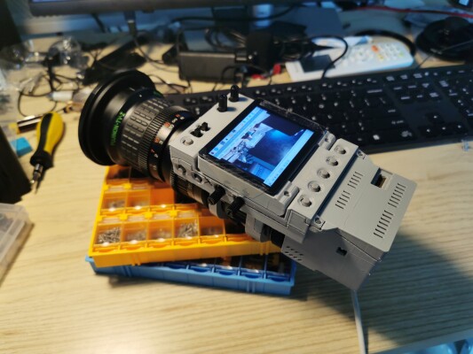
| #2230 | Digital 8mm Video CameraThis is a digital 8mm video camera made with a IMX462 module and a raspberry pi compute module. This device has the following notable features:
You are welcomed to make this camera yourself. Depending on the availability of components, you might need to modify the topology of the circuit or the structure of the shell. Following sections of this page contains notable instructions for assembling the device by yourself. Resources for download is listed at the bottom of this page. | |||||||||||||||||||||||||
| #2232 | Module TopologyFor designs with RPi CM4 as the main module, use the following peripherals and connections. Note that the waveshare expansion board use the same connection on the SD card slot as the CM4 on-board eMMC, so those two devices can not be used at the same time. Because the sound card takes the only USB port available on the expansion board, if you need a large storage, consider using a large SD card with the OS on it. The waveshare expansion board does have a 3.5mm stereo output jack, but I broke it when installing the casing. If you managed to not break it when assembling (technically you need to grind off part of the socket that extrudes beyond the circuit board), then you can use it to do audio monitoring.
[ Sirui 1.25x Ana  ]
[ Fujinon Th16x5.5 ]
       |
       | C-Mount      [ IR Cutter ]
       |                    |
[ Veye IMX462 ] ------------+
       |
 CSI-2 |   +--- i2c0 --- [ PCF 8575 ] ---- [ 12x Switches ]
       |   |
[ Waveshare CM4-Nano-B ] ------- [ SD Card ]
     | | | |
     | | | +--- i2c0 --- [ ADS 1115 ] ---- [ 4x Knobs ]
     | | |
     | | +----- DSI ----- [ Waveshare 2.8inch DSI screen ]
     | |
     | +----- USB ------- [ JMTek Sound Card ]
     |                             |
  [ RPi CM4 ]                      |
       |                    [ Comica VS-10 ]
       |
    [ eMMC ]
| |||||||||||||||||||||||||
| #2233 | Notes on Software ConfigurationDigital 8mm Video Camera runs "Retro Cam" program. This program supports capturing and recording video from For Raspberry Pi CM4 main board, it seems that the When starting Retro Cam for the first time, you need to set hardware port and address on the camera settings page. For the CM4 main board on the Digital 8mm Video Camera, you need to set the port to 0 and address to 59. If you are using raspberry pi 5 as the main board, depending on the camera port you have connected, the port number is either 6 (CSI-0) or 4 (CSI-2). When exiting the program, camera status as well as all the settings are saved. In Retro Cam program, clicking the top right arrow button to go to full screen. In the bottom center of the camera interface, press the upwards arrow to maximize the camera previewing area to the entire window (clicking it again to restore). This is useful when you have a small screen. If for whatever reason you have different i2c address for the camera/io-expander/adc board to what described below, you need to re-compile Retro Cam using the values you have on your devices. | |||||||||||||||||||||||||
| #2236 | Hardware NotesShellThe space above the folding screen is very limited. When making my device I left plenty of wires, this means they all have to go underneath the folding screen. Currently the old top cover is squeezing in pretty tightly with a bit buckling. You should choose appropriate length and thickness for your wires. If you decide to custom manufacture FFC boards, then this should not really be an issue. There are some small optimizations for FDM printers that are yet to be added to the model, like removing strengtheners on the shell section around the image sensor module, providing extra slot for headphone socket etc. Due to dimensional constraints there's no screw holes on the shell for fixing the screen module in place. Ideally you should use some kind of glue similar to those used on smartphones to glue it in place. You should install the IR-Cut lens mount onto the sensor board first, then plug in the board to the socket in the shell. The monolithic design of the shell makes it impossible to access screw holes for the sensor board once it's in place. If you want to have easy access to the screw, modification to the shell is then needed. Please try to use IR-Cut lens mount for CS lenses, and install a C-CS mount adapter ring after installing the sensor board in place, otherwise the assembly may not fit in the opening of the shell. Sound CardJMTek sound card board will connect directly to the only USB port on the expansion board, solder wires onto the pins of the USB socket would do the job. Due to this, you can only record pictures and videos onto the same physical device that your OS is on. Note that you need to remove PCF8575 boardYou can connect the interrupt output to one of the unoccupied GPIOs on the expansion board for receiving notifications when button states have been changed. PCF8575 does not have strong internal pull-ups. All input pins on PCF8575 must have pull-up resistors, and switches will be pulling the pin low to the ground. When connected correctly, the device should show on your i2c bus as 0x20. ADS1115 boardI selected a very small board for this. If you happened to be using a bigger one, you may want to adjust the shell for extra space. When connected correctly, the device should show on your i2c bus as 0x48. | |||||||||||||||||||||||||
| #2253 | More InformationDigial 8mm Video Camera is designed by Wu Yiming. You could download the 3d file for the shell of this camera and manufacture it yourself. All shell files are licensed with CC-BY 4.0↗ The files below are slightly modified compared to what you have seen in the posts, this is to better handle the dimension of existing parts, making it easier to print and also provide better handling.
Other links: | |||||||||||||||||||||||||
2024/08/01 15:38:36
2024/09/12 18:04:57 | ||||||||||||||||||||||||||
NewslettersEnter your email: | ||||||||||||||||||||||||||


